Bolt
Robot / hardware buildA six-actuator research biped with passive ankles, tethered power/data and no active yaw control. [1]
Build & first use →Official websiteBill of materials
- For
- Legged robotics laboratories; Builders with precision assembly and embedded-control experience [1]
- Source rights
- Named licenses are documented by part. Review licenses
- Unknowns
- operating system not fully established. Review gaps
Source researched · Not tested by us
Sources checked · Research details

Licenses & related hardware
- License
- BSD-3-Clause, BSD-2-Clause · Details by part
Overview
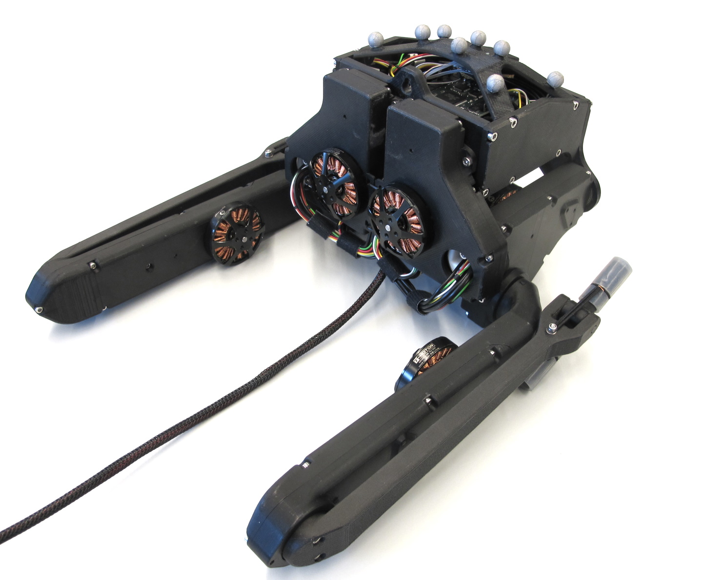
Bolt's documented body has two legs with three active degrees of freedom each and a passive ankle joint. There is no active leg-rotation axis, so the design documentation says yaw cannot be controlled directly. Its line-contact feet help stabilize that orientation. This is a specific constraint when choosing a locomotion experiment, rather than a general-purpose humanoid configuration. [5]
Is this for you?
- Known limitations
- No active leg rotation axis, so yaw cannot be directly controlled
- Published photographs explicitly identify string support
- Optional Vicon tracking infrastructure and exact control stack not included in a body-parts price
- No physical reproduction or support qualification
3D preview
Body structure — bottom. One bottom body-structure component from the biped 6-DOF v1 design (Bolt), not a complete robot. Upstream lists this STL under 3D Printed Parts; printing and scale have not been validated by us.
The 3D preview loads after the page.
Drag to orbit · Scroll or pinch to zoom · Right-drag to pan. Use the view buttons for front, side and top views. The tree shows names supplied by the source; unnamed bodies remain labeled as such.
Download original STL · File checksums and provenance
This model contains one geometric body.
Model sources
The preview uses the linked original design. Source grouping is retained where present; the caption identifies whether this is an assembly or one component.
Source, license and scale
Source: Max Planck Gesellschaft and New York University, revision 66af1522b4fba0ec4a1d7790e66f5e4652208d30. Original and preview: BSD-3-Clause. Preview conversion by Open Source Robotics; original file unchanged. Preview coordinates are centered and rounded to six decimal places. STL does not declare units; confirm dimensions against the project design. No physical part tested.
Viewer: three-cad-viewer 5.0.7 (MIT license). Confirm scale and manufacturing settings before printing.
What you need
Hardware & parts
Upstream bill of materials [5] [6] [7] [8] [9] [11] [13]
- Hardware configuration
Biped with three active axes per leg and a passive ankle
- Actuators
- Modular brushless actuator cores with dual-stage belt transmission
- Controller
Master Board v2 with three Micro Driver v2 boards in the documented BOM
Assembly & first use
Cost
No current, complete configuration-specific build cost has been established for this profile.
Project notes
The small body is only part of the experimental setup
The hardware guide describes an interface wire carrying power and Ethernet, a Master Board, three Micro Driver boards and an IMU. It also offers body-top variants with Vicon marker mounts; those markers are optional and only relevant to a motion-capture setup. The pictured standing robot is explicitly described as held by a string. Neither that photograph nor the preserved CAD establishes unsupported standing in our own tests. [5]
Each leg is a custom assembly using the shared brushless actuator cores. The core combines an optical encoder and two belt-reduction stages. A supplier encoder-kit route can replace machining and shaft preparation, but the documented build still needs fitting, threaded inserts, wiring and actuator assembly. Current sourcing and an exact delivered budget have not been checked. [5] [7] [8]
Include calibration and programming equipment
The shared calibration guide includes a biped-specific printed fixture. At startup the joint angles are unknown; the procedure uses rough manual alignment, encoder-index search and previously measured offsets. Repairing or replacing an actuator requires measuring the affected offset again. That is recurring maintenance work to measure during a build trial. [6]
The separately preserved Master Board release includes firmware and an SDK, but it is not a complete matched biped controller. Its documented host connection uses a dedicated Ethernet interface or specially supported raw wireless communication, and the reviewed flashing instructions specify ESP-IDF 3.x compatibility, using an installer from 4.0.1 before rolling back to commit 8d1a9c0. They also require a USB-to-serial programming arrangement with accessible RTS/DTR signals and reset circuitry. The Micro Drivers use a separate XDS100V2 JTAG emulator and adapter cable. The robot, host, motor-driver firmware and chosen control program must therefore be versioned together before a reproduction claim. [9] [11] [12] [13]
The mechanical and Micro Driver documentation carries BSD-3-Clause terms, while the Master Board has BSD-2-Clause terms. Purchased parts and other control dependencies still need separate checks. No assembly, balance control, calibration or support workload was tested here. [3] [11]
What we checked
Source research only; no installation, physical build or performance test performed. No affiliate links added.
Not yet established
- Requirements: operating system
- A step-by-step setup summary
Updates
- Upstream last updated
- Sep 6, 2022 [2]
- Latest release
- Not established
- Profile updated
- Oct 25, 2026
- Sources last checked
- Sep 30, 2026
- Next review
- Oct 30, 2026
- Reviewed revision
- 66af1522b4fba0ec4a1d7790e66f5e4652208d30 (commit snapshot; no published stable release found) · combined hardware and software repository
Source files and licenses
Available project sources support research coverage; complete build and commercial qualification remain separate.
| Layer | Availability / license |
|---|---|
| mechanical design | available · BSD-3-Clause Hardware repository scope; separately hosted boards and purchased components retain their own terms. [3] [5] [9] |
| electronics | available · BSD-3-Clause Hardware repository scope; separately hosted boards and purchased components retain their own terms. [3] [5] [9] |
| firmware | available · BSD-2-Clause Master Board repository only; not a complete robot control/dependency pack. [11] [12] [13] |
| software | available · BSD-2-Clause Master Board repository only; not a complete robot control/dependency pack. [11] [12] [13] |
| documentation | available · BSD-3-Clause Hardware repository scope; separately hosted boards and purchased components retain their own terms. [3] [5] [9] |
No particular learned controller or dataset selected in this hardware review.
References
Each source links to the exact revision we read. “Used for” shows where this page relies on it.
Project sources
- S001 open-dynamic-robot-initiative/open_robot_actuator_hardware: README.md
Revision, date & where cited
github.com · revision
66af152· Accessed Sep 30, 2026 - S002 open-dynamic-robot-initiative/open_robot_actuator_hardware: commit 66af152
- S003 open-dynamic-robot-initiative/open_robot_actuator_hardware: LICENSE
Revision, date & where cited
github.com · revision
66af152· Accessed Sep 30, 2026
Used for: Include calibration and programming equipment, Source files and licenses - S004 open-dynamic-robot-initiative/open_robot_actuator_hardware: files
Revision, date & where cited
github.com · revision
66af152· archive file inventory · Accessed Sep 30, 2026 - S009 electronics/micro_driver_electronics/README.md
Revision, date & where cited
github.com · revision
66af152· Accessed Sep 30, 2026
Used for: What you need, Hardware & parts, Assembly & first use, Include calibration and programming equipment and 1 more - S007 mechanics/actuator_module_v1/actuator_module_v1.1.md
Revision, date & where cited
github.com · revision
66af152· Accessed Sep 30, 2026
Used for: What you need, Hardware & parts, Assembly & first use, The small body is only part of the experimental setup - S008 mechanics/actuator_module_v1/details/details_tools.md
Revision, date & where cited
github.com · revision
66af152· Accessed Sep 30, 2026
Used for: What you need, Hardware & parts, Assembly & first use, The small body is only part of the experimental setup - S005 mechanics/biped_6dof_v1/README.md
Revision, date & where cited
github.com · revision
66af152· Accessed Sep 30, 2026
Used for: Overview, Is this for you?, What you need, Hardware & parts and 3 more - S006 mechanics/general/robot_calibration.md
Revision, date & where cited
github.com · revision
66af152· Accessed Sep 30, 2026
Used for: What you need, Hardware & parts, Assembly & first use, Include calibration and programming equipment - S011 Master Board release and license
Revision, date & where cited
github.com · revision
ab2c717· README and LICENSE at · Accessed Sep 30, 2026
Used for: What you need, Hardware & parts, Assembly & first use, Include calibration and programming equipment and 1 more - S012 firmware/README.md
Revision, date & where cited
github.com · revision
ab2c717· Accessed Sep 30, 2026
Used for: Include calibration and programming equipment, Source files and licenses - S013 sdk/master_board_sdk/README.md
Revision, date & where cited
github.com · revision
ab2c717· Accessed Sep 30, 2026
Used for: What you need, Hardware & parts, Assembly & first use, Include calibration and programming equipment and 1 more - S018 Upstream image and reuse attribution
Media-only review: Upstream photograph of the Bolt six-degree-of-freedom biped configuration. Reuse basis: BSD-3-Clause; inspected LICENSE and the pinned file inventory for nearer notices. Original image unchanged; displayed responsively. This does not refresh technical or cost evidence.Revision, date & where cited
Open Dynamic Robot Initiative, New York University and Max Planck Gesellschaft · github.com · revision
66af152· Image SHA-256 f05ecafecf27c6cbf57cf977f9c37df1a8fbb158405ad8b740dddb372da45e1f; repository · Accessed Oct 25, 2026
Videos
- S014 Open Dynamic Robot Initiative (YouTube channel)
The project’s own YouTube channel, linked from the project’s own documentation. Not reviewed by us for accuracy.Revision, date & where cited
YouTube channel Open Dynamic Robot Initiative · youtube.com · Accessed Oct 4, 2026
- S015 Integration test: 3DM-CX5-25 IMU + Motor control - Closed loop via Ethernet (YouTube video)
Video from the project’s own channel (Open Dynamic Robot Initiative), linked from the project’s own documentation. Not reviewed by us for accuracy.Revision, date & where cited
YouTube video Open Dynamic Robot Initiative · youtube.com · Accessed Oct 4, 2026
- S016 Master board first wireless tests (YouTube video)
Video from the project’s own channel (Open Dynamic Robot Initiative), linked from the project’s own documentation. Not reviewed by us for accuracy.Revision, date & where cited
YouTube video Open Dynamic Robot Initiative · youtube.com · Accessed Oct 4, 2026
- S017 20180914 Optical Foot Contact Switch Demonstration (YouTube video)
Video from the project’s own channel (Open Dynamic Robot Initiative), linked from the project’s own documentation. Not reviewed by us for accuracy.Revision, date & where cited
YouTube video Open Dynamic Robot Initiative · youtube.com · Accessed Oct 4, 2026
Correction guidance · Discussion is not enabled · Profile format 0.5.0-draft.1
Change history
2026-10-04 — Added 4 YouTube reference(s) (S014, S015, S016, S017): official channel or videos linked from the pinned upstream sources. Existing claims, source-check dates and evidence are unchanged.
2026-10-25 — Added an attributed upstream image with linked reuse terms; technical evidence dates unchanged.