moteus
Motor controllerOpen brushless servo-controller designs with CAN-FD control, board-specific electrical limits and motor calibration requirements. [1]
Build & first use →Official website
- For
- Robotics developers integrating brushless motors and feedback [1]
- Cost
- No current cost or bill of materials established yet.
- Source rights
- Named licenses are documented by part. Review licenses
- Unknowns
- tools not fully established. Review gaps
Source researched · Not tested by us
Sources checked · Research details

Licenses & related hardware
- License
- Apache-2.0 · Details by part
Overview
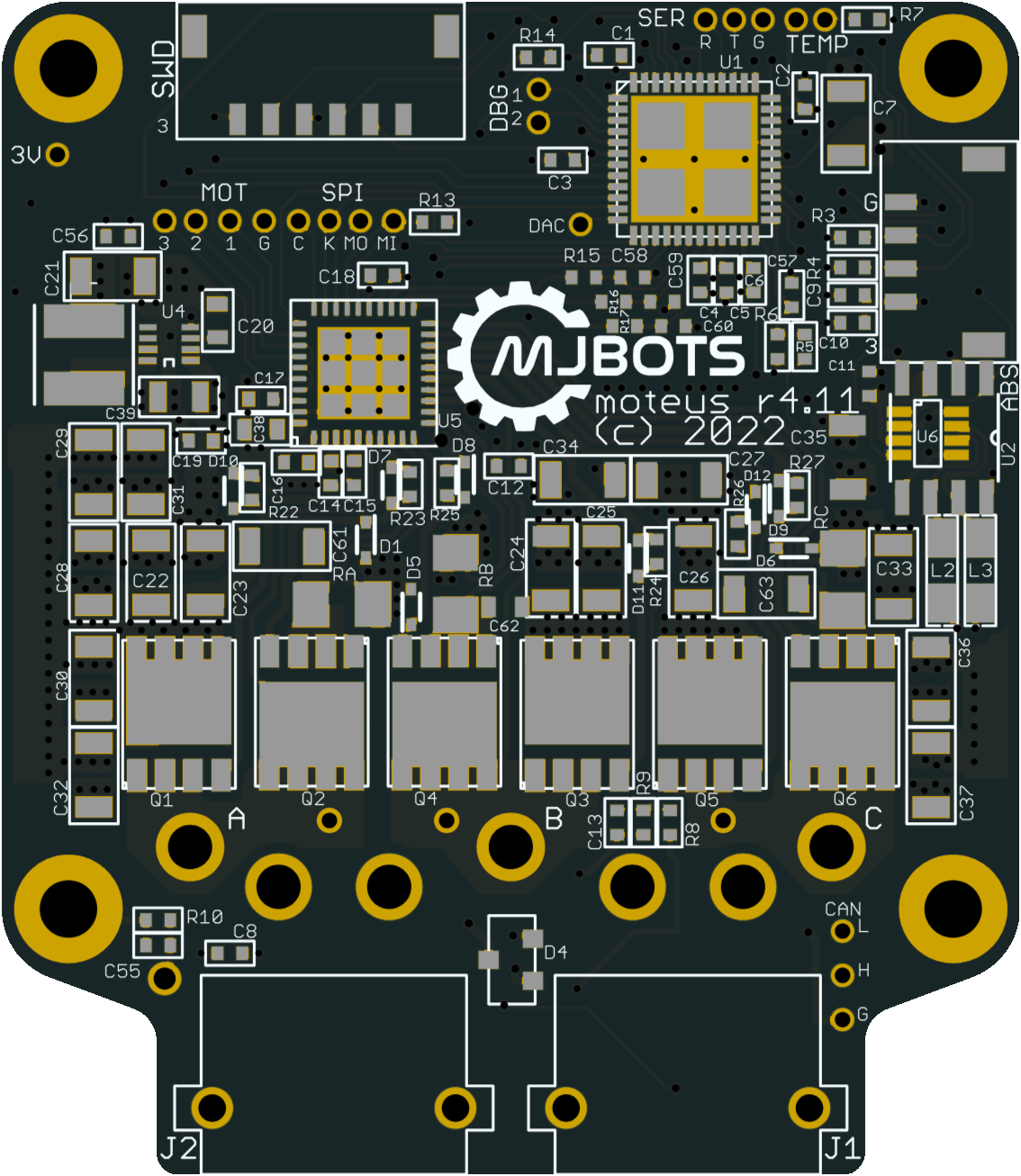
moteus provides brushless servo-controller hardware designs, firmware and host libraries. It is a component for building an actuator: the motor, mechanical mounting, power system and host connection still need to be selected. The preserved repository covers r4.11, c1, n1 and x1 boards with different electrical and thermal limits. A specification from one column should not be applied to another board. [1]
Is this for you?
- Known limitations
- Board variants have different voltage, current and cooling limits
- Bare-board configuration does not establish a complete actuator budget
- Normal calibration requires an unloaded rotor able to turn freely
Integration boundaries derived from the documented hardware and calibration route.
3D preview
moteus n1 r1.3 board mechanical model. One component: the simplified single-body mechanical model of the moteus n1 r1.3 controller board published by mjbots in hw/n1/r1.3. Board outline, mounting holes and simplified envelope blocks for connectors and larger components are fused into one body; it is not a component-accurate board assembly. Other moteus boards (r4.11, c1, x1) have different outlines and ratings; the pinned tree has no r4.11 mechanical STEP. Apache-2.0 per the repository README; mjbots and moteus are trademarks of mjbots Robotic Systems LLC. Electrical function and fit are not verified.
The 3D preview loads after the page.
Drag to orbit · Scroll or pinch to zoom · Right-drag to pan. Use the view buttons for front, side and top views. The tree shows names supplied by the source; unnamed bodies remain labeled as such.
Download original STEP (gzip) · File checksums and provenance
This model contains one geometric body.
Model sources
The preview uses the linked original design. Source grouping is retained where present; the caption identifies whether this is an assembly or one component.
Source, license and scale
Source: mjbots Robotic Systems, revision fdc6e318194443213c669d28d72e40be38147d2b. Original and preview: Apache-2.0. Preview conversion by Open Source Robotics; original file unchanged. Preview coordinates are centered and rounded to six decimal places. STEP preview triangulated in millimetres. No physical part tested.
Viewer: three-cad-viewer 5.0.7 (MIT license). Confirm scale and manufacturing settings before printing.
What you need
Hardware & parts
Assembly & first use
Cost
No current, complete configuration-specific build cost has been established for this profile.
Project notes
Board ratings are not a complete actuator rating
For example, the overview lists a 10–44 V input range for r4.11 and 10–54 V for n1 and x1. It distinguishes uncooled, cooled and peak phase current. Those are upstream board figures, not a measured continuous torque rating for a motor, gearbox or assembled robot. The hardware archive includes revisioned board designs and some mechanical models; this review did not validate their geometry or fabrication outputs. [1] [12]
The onboard encoder route needs a diametrically magnetized magnet fixed to the motor rotor, with the board rigidly centered above it at approximately a 2 mm gap. The r4 encoder is offset from the mounting-hole pattern. The n1 guide also calls for an opaque enclosure because its regulator is light-sensitive. These are variant-specific mounting requirements, not interchangeable enclosure advice. [5]
Power integration comes before motion
The electrical guide calls out absent reverse-polarity protection, inrush management and avoiding hot-plugged XT30 connections. Braking returns energy to the DC bus, so a supply that can only source current may be insufficient. Regeneration settings, energy absorption and voltage headroom must be considered together for the selected load. Software limits alone do not establish a validated power system. [6]
CAN wiring, termination and connector quality also matter, especially as the number of controllers increases. The guide recommends a different power-distribution arrangement beyond three devices on a chain. A controller purchase therefore does not cover the cost or design of a multi-joint power and communications system. [6]
Configure, calibrate and then tune
The documented host tools include moteus-gui and its tview interface on Linux, Windows and macOS. Linux USB adapters may need device-access rules. These installation instructions were inspected but not executed. [7]
Before motion, choose application-specific position, phase-current, velocity and acceleration limits, gear scaling and a unique CAN-FD ID. Bare boards leave default velocity and acceleration limits unset. Parameter edits are volatile until saved with conf write; a working session is not proof that its configuration will survive a restart. [8]
Bare boards require calibration for the attached motor, repeated after a motor change or a change in its registration with the controller. The normal procedure rotates the unloaded motor in both directions and includes high-speed motion. Calibration power must suit the motor; the documented default is not appropriate for every size. Development kits are typically pre-calibrated, which does not carry over automatically to a modified motor assembly. Position-loop tuning follows calibration and should use physically achievable acceleration limits. [9] [10]
Firmware releases distinguish the application ELF from the CAN bootloader ELF. Normal CAN flashing uses the application image; bootloader recovery is a separate SWD procedure. The source-build guide specifies x86-64 Ubuntu 22.04, 24.04 or 26.04 and a Bazel route. Its printed dependency-install line is incomplete as a shell command, so this profile does not present that sequence as a tested installation recipe. [11]
What is open, and what remains to be supplied
The repository declares Apache-2.0 for files unless otherwise noted and contains board designs, firmware, client software and documentation. External components and dependencies need their own license assessment; the project names also have a separate trademark policy. A complete delivered budget remains unknown because it depends on the selected board, motor, magnet, mounting, cooling, power equipment, adapter and tools. No board was manufactured, firmware flashed, motor calibrated or performance measured for this profile. [1] [3] [5] [6] [7] [12]
What we checked
Source research only; no installation, physical build or performance test performed. No affiliate links added.
Not yet established
- Requirements: tools
- A step-by-step setup summary
Updates
Source files and licenses
Available project sources support research coverage; complete build and commercial qualification remain separate.
| Layer | Availability / license |
|---|---|
| mechanical design | available · Apache-2.0 Board mechanical drawings/models for selected revisions; not a complete motor, gearbox or robot design. Geometry not inspected. [1] [3] [12] |
| electronics | available · Apache-2.0 Repository default unless otherwise noted; external dependencies and purchased parts retain their own terms. No manufacturing or execution verified. [1] [3] [12] |
| firmware | available · Apache-2.0 Repository default unless otherwise noted; external dependencies and purchased parts retain their own terms. No manufacturing or execution verified. [1] [3] [12] |
| software | available · Apache-2.0 Repository default unless otherwise noted; external dependencies and purchased parts retain their own terms. No manufacturing or execution verified. [1] [3] [12] |
| documentation | available · Apache-2.0 Repository default unless otherwise noted; external dependencies and purchased parts retain their own terms. No manufacturing or execution verified. [1] [3] [12] |
Selected motor-control route does not require a learned policy or training dataset.
References
Each source links to the exact revision we read. “Used for” shows where this page relies on it.
Project sources
- S001 mjbots/moteus: README.md
Revision, date & where cited
github.com · revision
fdc6e31· Accessed Oct 1, 2026
Used for: Overview, Is this for you?, Hardware & parts, Assembly & first use and 3 more - S002 mjbots/moteus: commit fdc6e31
- S003 mjbots/moteus: LICENSE
Revision, date & where cited
github.com · revision
fdc6e31· Accessed Oct 1, 2026
Used for: What is open, and what remains to be supplied, Source files and licenses - S004 mjbots/moteus: files
Revision, date & where cited
github.com · revision
fdc6e31· archive file inventory · Accessed Oct 1, 2026 - S005 docs/guides/mechanical-setup.md
Revision, date & where cited
github.com · revision
fdc6e31· Accessed Oct 1, 2026
Used for: What you need, Board ratings are not a complete actuator rating, What is open, and what remains to be supplied - S006 docs/guides/electrical-setup.md
Revision, date & where cited
github.com · revision
fdc6e31· Accessed Oct 1, 2026
Used for: What you need, Power integration comes before motion, What is open, and what remains to be supplied - S007 docs/guides/software-installation.md
Revision, date & where cited
github.com · revision
fdc6e31· Accessed Oct 1, 2026
Used for: What you need, Configure, calibrate and then tune, What is open, and what remains to be supplied - S008 docs/guides/configuration.md
Revision, date & where cited
github.com · revision
fdc6e31· Accessed Oct 1, 2026
Used for: Configure, calibrate and then tune - S009 docs/guides/calibration.md
Revision, date & where cited
github.com · revision
fdc6e31· Accessed Oct 1, 2026
Used for: Is this for you?, What you need, Assembly & first use, Configure, calibrate and then tune - S010 docs/guides/pid-tuning.md
Revision, date & where cited
github.com · revision
fdc6e31· Accessed Oct 1, 2026
Used for: Assembly & first use, Configure, calibrate and then tune - S011 docs/reference/firmware.md
Revision, date & where cited
github.com · revision
fdc6e31· Accessed Oct 1, 2026
Used for: Configure, calibrate and then tune - S012 Complete archive inventory
Revision, date & where cited
github.com · revision
fdc6e31· Preserved archive file inventory · Accessed Oct 1, 2026
Used for: Board ratings are not a complete actuator rating, What is open, and what remains to be supplied, Source files and licenses - S016 Upstream image and reuse attribution
Media-only review: Upstream photograph of a moteus controller board; board revisions and connectors vary by configuration. Reuse basis: Apache-2.0; inspected LICENSE and the pinned file inventory for nearer notices. Original image unchanged; displayed responsively. This does not refresh technical or cost evidence.Revision, date & where cited
mjbots and moteus contributors · github.com · revision
fdc6e31· Image SHA-256 5fd941520afdb5a436f985894dc4e1708e1a1b151864de7c38b9542a72c1ce46; repository · Accessed Oct 25, 2026
Videos
- S013 How to build custom XT30 cables (YouTube video)
Video from the project’s own channel (Josh Pieper), linked from the project’s own documentation. Not reviewed by us for accuracy.Revision, date & where cited
YouTube video Josh Pieper · youtube.com · Accessed Oct 4, 2026
- S014 Soldering phase wires to the moteus controller (YouTube video)
Video from the project’s own channel (Josh Pieper), linked from the project’s own documentation. Not reviewed by us for accuracy.Revision, date & where cited
YouTube video Josh Pieper · youtube.com · Accessed Oct 4, 2026
- S015 Josh Pieper (YouTube channel)
The project’s own YouTube channel, found by searching YouTube and checked against the channel page. Not reviewed by us for accuracy.Revision, date & where cited
YouTube channel Josh Pieper · youtube.com · Accessed Oct 4, 2026
Correction guidance · Discussion is not enabled · Profile format 0.6.0-draft.1
Change history
2026-10-04 — Added 3 YouTube reference(s) (S013, S014, S015): official channel or videos linked from the pinned upstream sources. Existing claims, source-check dates and evidence are unchanged.
2026-10-25 — Added an attributed upstream image with linked reuse terms; technical evidence dates unchanged.