Just1
Robot / hardware buildRaspberry Pi mecanum robot with ROS 2 navigation using lidar and an IMU; its published wheel commands are not measured wheel speeds. [1] [8] [9]
Build & first use →Official websiteBill of materials
- For
- Builders comfortable with printed parts, Raspberry Pi wiring and ROS 2 setup [1]
- Cost
- No current cost yet. Upstream bill of materials [6]
- Source rights
- Some licenses are unresolved. Review licenses
- Unknowns
- tools not fully established. Review gaps
Source researched · Not tested by us
Sources checked · Research details

Licenses & related hardware
- License
- MIT · license not fully assessed for mechanical design, electronics · Details by part
Overview
Is this for you?
- Known limitations
- Upstream reports obstacles below 20 cm are not detected by the mounted lidar
- Wheel encoders are a future improvement
- Camera starts in both manual and autonomous launch modes despite being optional hardware
- No complete current delivered cost or reproduced navigation performance verified
3D preview
Just1 source assembly. The source STEP assembly, including supplied purchased-component representations. This is a visual reference; exact component revisions, physical fit and a working build have not been verified.
The 3D preview loads after the page.
Drag to orbit · Scroll or pinch to zoom · Right-drag to pan. Use the view buttons for front, side and top views. The tree shows names supplied by the source; unnamed bodies remain labeled as such.
Download original STEP (gzip) · File checksums and provenance
Separate bodies can be inspected in the model tree. Explode is a viewing aid, not an assembly sequence.
Model sources
The preview uses the linked original design. Source grouping is retained where present; the caption identifies whether this is an assembly or one component.
Source, license and scale
Source: Nicolas Rodriguez / Just1 contributors, revision a00abd6e85358cd43f39f26393cbea04c65af20d. Original and preview: MIT. Preview conversion by Open Source Robotics; original file unchanged. Preview coordinates are centered and rounded to six decimal places. STEP preview triangulated in millimetres. No physical part tested.
Viewer: three-cad-viewer 5.0.7 (MIT license). Confirm scale and manufacturing settings before printing.
What you need
Hardware & parts
Assembly & first use
- Assembly
Print the supplied STL parts, use the STEP assembly as a reference and wire the separate Pi and motor power supplies.
Cost
No current, complete configuration-specific build cost has been established for this profile.
Project notes
Build around the documented power and parts choices
The hardware guide selects an 8 GB Pi 4, four TT motors, two L298N drivers and 60 mm mecanum wheels. It separates the Pi's 5 V, 3 A power bank from the six-AA motor battery holder. A rechargeable motor supply is mentioned as a future alternative, not a fully specified replacement configuration. The repository includes a STEP assembly, printable STL components and wiring diagrams, but their presence is not a fit or electrical test. [4] [5] [6]
The $250 headline comes from a March 2025 US parts table. That table assumes access to free chassis printing and lists screws, wires, spacers and a switch separately. A builder should price the chosen camera, printing, accessories, batteries and delivery before treating it as a complete budget. No current delivered build total was verified here. [6]
Follow the selected software route
The setup guide targets Ubuntu Server 24.04 and ROS 2 Jazzy, with RTAB-Map, Nav2, the Madgwick filter and Foxglove bridge. Its camera setup builds libcamera and libcamera-apps from source. Those clone instructions do not pin dependency revisions, so preserving this project commit alone does not preserve the complete installation. No installation commands were run in this review. [2] [7]
The launch file provides manual, diagnostics and autonomous modes. In autonomous mode, Foxglove is used to inspect the map and publish navigation goals. There is an important optional-camera detail: the hardware guide calls the camera optional, but the launch file starts the camera node in both manual and autonomous modes. Omitting the camera therefore calls for checking and adapting that launch configuration; this review does not claim a tested camera-free setup. [5] [7] [10]
Read wheel commands and odometry differently
The autonomous motor controller converts velocity commands into wheel RPM using fixed wheel radius and chassis dimensions, then converts those RPM values to bounded motor percentages. Its wheel_speeds message contains calculated RPM commands, not encoder feedback. Adding wheel encoders is still listed as a future improvement in the overview. [1] [9]
The node documentation describes lidar scan matching and IMU data as the input to ICP odometry. Consequently, a wheel command does not demonstrate that the robot actually moved at that speed. The provided diagnostics mode can help a builder check individual wheels and movements, while sensor transforms must match the physical installation. This commissioning sequence is an editorial recommendation, not a test performed here. [8] [9] [10]
Upstream reports that the lidar placement misses obstacles below 20 cm. It also reports high CPU utilization during navigation, with RTAB-Map, Nav2 and the camera contributing load. Those observations are useful constraints for an indoor experiment, but this review does not establish collision avoidance reliability, achieved speed or available computing margin. [1] [7]
What the source release covers
The root license is MIT for software and associated documentation. Third-party driver code and dependencies retain their own terms. The archive includes STEP, STL and wiring artifacts, but this review did not establish a separate hardware-design grant or complete source for the purchased electronics. No printed assembly, power system, calibration or navigation test was performed. [3] [4] [5]
What we checked
Source research only; no installation, physical build or performance test performed. No affiliate links added.
Not yet established
- Requirements: tools
- A step-by-step setup summary
Updates
- Upstream last updated
- Nov 9, 2025 [2]
- Latest release
- Not established
- Profile updated
- Oct 25, 2026
- Sources last checked
- Oct 1, 2026
- Next review
- Oct 31, 2026
- Reviewed revision
- a00abd6e85358cd43f39f26393cbea04c65af20d (commit snapshot; no published stable release found) · combined hardware and software repository
Source files and licenses
Available project sources support research coverage; complete build and commercial qualification remain separate.
| Layer | Availability / license |
|---|---|
| mechanical design | available · License not fully assessed STEP assembly and printable STL files present; no separate explicit hardware-design license established. [4] [5] |
| electronics | available · License not fully assessed Wiring diagrams and editable Excalidraw file present; purchased electronics source not established. [4] [5] |
| firmware | not found · License not fully assessed No complete firmware source for the purchased lidar, Pi or other electronics established in this archive. [4] |
| software | available · MIT Root software license; vendored lidar driver and external dependencies retain their own notices and terms. [3] [4] |
| documentation | available · MIT Root license covers associated documentation; linked external materials separate. [3] [4] |
Selected lidar/IMU navigation route does not use a downloaded learned policy or training dataset.
References
Each source links to the exact revision we read. “Used for” shows where this page relies on it.
Project sources
- S001 NRdrgz/Just1: README.md
Revision, date & where cited
github.com · revision
a00abd6· Accessed Oct 1, 2026
Used for: Overview, Is this for you?, What you need, Hardware & parts and 2 more - S002 NRdrgz/Just1: commit a00abd6
Revision, date & where cited
github.com · Accessed Oct 1, 2026
Used for: Follow the selected software route, What we checked - S003 NRdrgz/Just1: LICENSE
Revision, date & where cited
github.com · revision
a00abd6· Accessed Oct 1, 2026
Used for: What the source release covers, Source files and licenses - S004 NRdrgz/Just1: files
Revision, date & where cited
github.com · revision
a00abd6· archive file inventory · Accessed Oct 1, 2026
Used for: Build around the documented power and parts choices, What the source release covers, Source files and licenses - S005 Just1: Bot/Hardware/README.md
Revision, date & where cited
github.com · revision
a00abd6· Accessed Oct 1, 2026
Used for: Overview, What you need, Hardware & parts, Assembly & first use and 4 more - S006 Just1: Bot/Hardware/Bill_of_material.md
Revision, date & where cited
github.com · revision
a00abd6· Accessed Oct 1, 2026
Used for: Is this for you?, Hardware & parts, Build around the documented power and parts choices - S007 Just1: Bot/Software/README.md
Revision, date & where cited
github.com · revision
a00abd6· Accessed Oct 1, 2026
Used for: Overview, What you need, Follow the selected software route, Read wheel commands and odometry differently - S008 Just1: Bot/Software/NodeDescription.md
Revision, date & where cited
github.com · revision
a00abd6· Accessed Oct 1, 2026
Used for: Assembly & first use, Read wheel commands and odometry differently - S009 Just1: Bot/Software/src/just1_motors/just1_motors/autonomous_controller_node.py
Revision, date & where cited
github.com · revision
a00abd6· Accessed Oct 1, 2026
Used for: Read wheel commands and odometry differently - S010 Just1: Bot/Software/src/just1_bringup/launch/just1.launch.py
Revision, date & where cited
github.com · revision
a00abd6· Accessed Oct 1, 2026
Used for: Is this for you?, Assembly & first use, Follow the selected software route, Read wheel commands and odometry differently - S012 Upstream image and reuse attribution
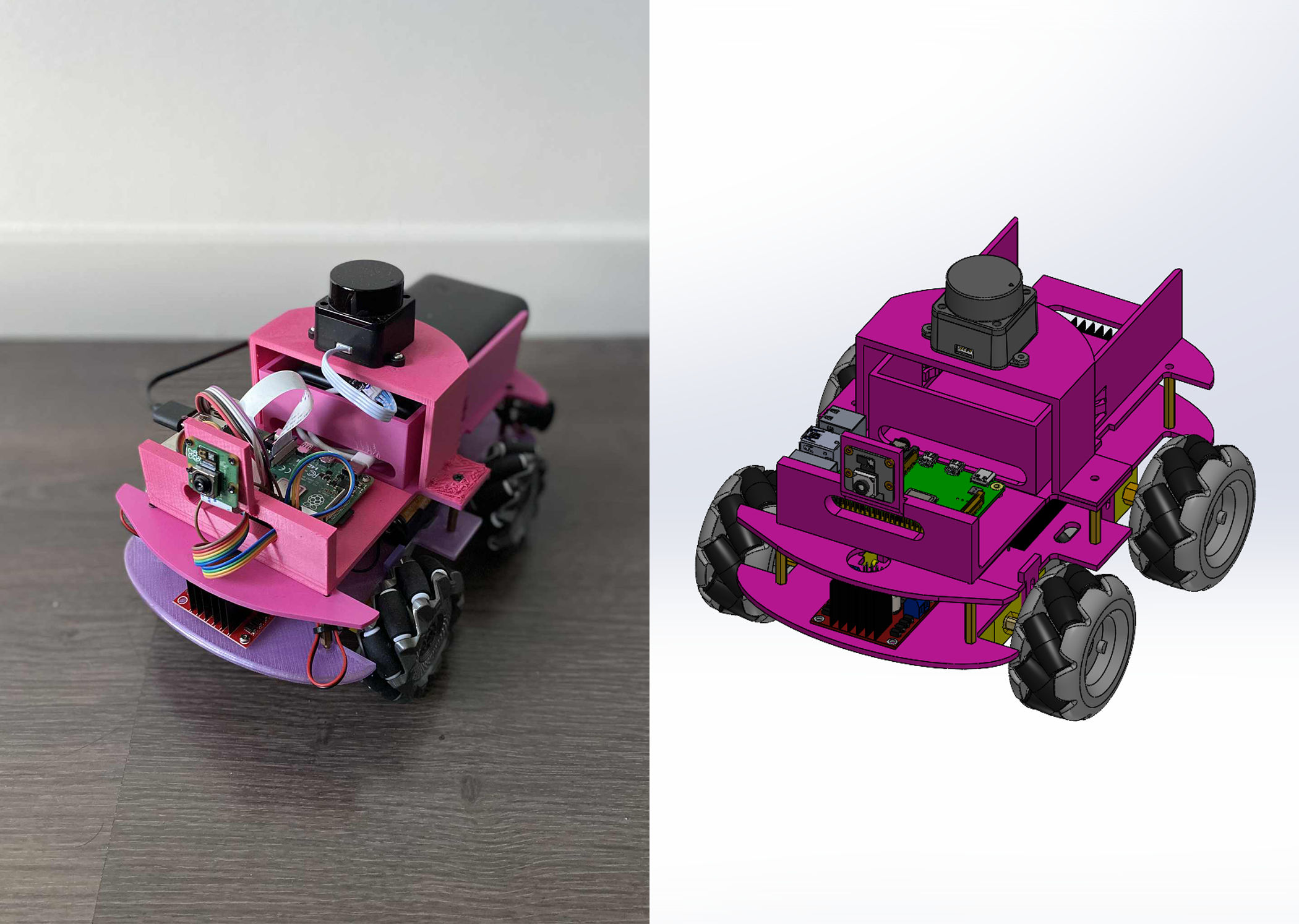
Media-only review: Upstream comparison image of a physical Just1 robot and its design visualization. Reuse basis: MIT; inspected LICENSE and the pinned file inventory for nearer notices. Original image unchanged; displayed responsively. This does not refresh technical or cost evidence.Revision, date & where cited
Nicolas Rodriguez and Just1 contributors · github.com · revision
a00abd6· Image SHA-256 e7470c93eda3abb08cd1bea71d8c3c3f634dcc6e7cba2f98a0cc1bb910765e69; repository · Accessed Oct 25, 2026
Videos
- S011 Just1 (YouTube video)
Video uploaded by Nico, linked from the project’s own documentation. Not reviewed by us for accuracy.Revision, date & where cited
YouTube video Nico · youtube.com · Accessed Oct 4, 2026
Correction guidance · Discussion is not enabled · Profile format 0.6.0-draft.1
Change history
2026-10-04 — Added 1 YouTube reference(s) (S011): official channel or videos linked from the pinned upstream sources. Existing claims, source-check dates and evidence are unchanged.
2026-10-25 — Added an attributed upstream image with linked reuse terms; technical evidence dates unchanged.